Online help
About software
Null modem overview
The purpose of a null-modem cable is to permit two RS-232 "DTE" devices to communicate with each other without modems or other communication devices (i.e., "DCE"s) between them.
To achieve this, the most obvious connection is that the TD signal of one device must be connected to the RD input of the other device (and vice versa). Also, however, many DTE devices use other RS-232 pins for out-of-band (i.e., "hardware") flow control. One of the most common schemes is for the DTE (the PC) to assert the RTS signal if it is ready to receive data (yes, it DOES sound backwards, but that's how it works), and for the DCE (the modem) to assert CTS when it is able to accept data. By connecting the RTS pin of one DTE to the CTS pin of the other DTE, we can simulate this handshake.
Also, it is common convention for many DTE devices to assert the DTR signal when they are powered on, and for many DCE devices to assert the DSR signal when they are powered on, and to assert the CD signal when they are connected. By connecting the DTR signal of one DTE to both the CD and DSR inputs of the other DTE (and vice versa), we are able to trick each DTE into thinking that it is connected to a DCE that is powered up and online.
Software overview
Virtual Null Modem (VNM) is an utility, which purpose is to emulate one or more RS232 serial ports connected via virtual null-modem cable. Otherwise, you can create any number of pure virtual serial ports in your system (COM10, COM11, COM255 etc), that will be connected to each other via virtual null-modem cable.
If you have two applications you want to connect to each other using serial ports you need a null modem. A null modem is bascially a cable to connect two serial ports to each other. Normally you need two computers or two physical ports on one computer to achive this. Using Virtual Null Modem software you can emulate the null modem and run the two applications on the same computer without any additional hardware.
Example:
You can create two virtual serial ports: COM10 and COM12 and connect two different applications to them. Everything, that application #1 will send to COM10 will be received by application #2 at COM12, and all that application #2 sends to COM12 will be received by application #1 at COM10.
Features:
•No reboot required. Creating, installing and removing of virtual serial ports occurs at real time;
•You can create any number of virtual serial ports pairs;
•Any other hardware or virtual serial ports are not used or occupied;
•You even can have no serial ports in your system;
•Other applications will never see the difference between real serial port and virtual serial ports, created by Virtual Null Modem software;
•The link between two virtual serial ports is faster then real null-modem cable connection and depends on your computer system speed;
•The virtual link is much more reliable than common physical link;
•Virtual Null Modem uses kernel driver technology and supports: WDM, WMI, Power Management, PNP, etc.;
•Virtual Null Modem software has a simple, menu-driven step by step set-up. Programming is not required to configure the software to configure virtual serial ports and virtual serial ports pairs;
•If you are software developer, then you can configure each port to sumulate a real-world data exchange with errors in data;
•You can add, remove virtual null modems from your application by using a command line interface.
DISCLAIMER:
We take no responsibility for any damage or injury caused by files written or edited with this software.
As the user has twenty one days to try this software with the full function demo version, warranty is limited to replacement of defective product.
For more information, to report bugs, or to make suggestions please see our website at www.aggsoft.com, or email support page.
Company home page: https://www.aggsoft.com/
Software home page: https://www.virtual-null-modem.com/
Serial port hardware reference: https://www.aggsoft.com/rs232-pinout-cable/
Limitations of the trial version
Trial version: 21 days trial limit, 65k of traffic
Licenses version: No limitations
System requirements
Processor: Any Intel® x86 compatible CPU
Operating system:
•Windows 2000;
•Windows 2000 Server;
•Windows XP (all editions) (both x86 and x64);
•Windows 2003 Server (both x86 and x64);
•Windows Vista (both x86 and x64).
•Windows 7 (both x86 and x64).
•Windows 2012 Server (both x86 and x64).
•Windows 10 (both x86 and x64).
•Windows 2016 Server (both x86 and x64).
The program doesn't work under Windows 9x,Me and NT!
CPU speed: Recommended 1 GHz or faster – our software may run successful on certain slower CPUs but because of Windows overhead, performance test results will not be as accurate.
Memory: Recommended 256 MB.
Free disk space: Virtual Null Modem takes up about 5 MB but additional space required for log files.
Special login requirements: You must be logged on as a user with Administrator privileges to run our software. It is necessary for access certain registry keys and plug/eject/install virtual serial ports.
Microsoft Vista notes:
Because our software uses a kernel-mode driver for creating virtual serial ports, therefore:
1.You need administrator privileges to run our software;
2.The desktop icon of our software will contain a shield (fig. 1);
3.Windows Vista will ask your permission to continue (fig. 2).
![]()
Fig. 1. Desktop icon on Windows Vista.
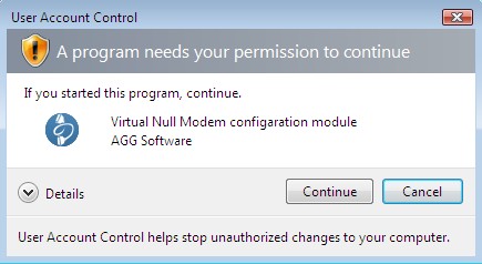
Fig. 2. User Account Control dialog.
You may disable User Account Control manager and you'll never see the dialog above. Please, search Google for a solution.
Installation
Unplug all virtual null modems if you are using Virtual Null Modem. Quit of the working Virtual Null Modem before installation.
If any beta-version was installed on your computer, remove it.
Run an installation file.
Follow the instructions of the wizard during the installation process.
By default, Virtual Null Modem will be installed to the directory"/Programs Files/Virtual Null Modem" of your system disk, but you can change this path.
Microsoft Windows 2003 notes:
During installation Windows will ask your permission twice to install the kernel mode driver (fig. 3). Please, set click the "Yes" button.
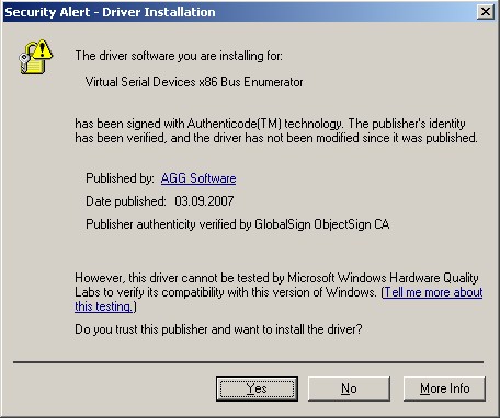
Fig. 3. Windows 2003 popup.
Microsoft Vista notes:
Before install Windows will ask your permission to install the software (fig. 4). Please, click the "Continue" button.
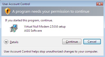
Fig. 4. Windows Vista.
During installation Windows will ask your permission to install the kernel mode driver (fig. 5). Please, set the "Always trust software from AGG Software" option and click the "Install" button.
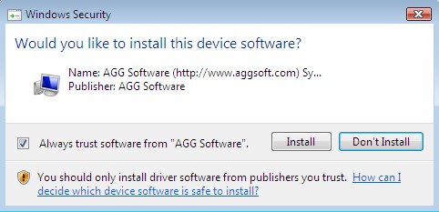
Fig. 5. Windows 7 and 8.
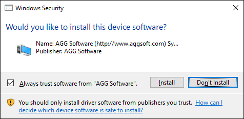
Fig. 6. Windows 10 and higher OS popup.
After you install the program, configure the program step by step as described below.
Introduction
Highlights
•No reboot required. Creating, installing and removing of virtual serial ports occurs at real time;
•You can create any number of virtual serial ports pairs;
•Any other hardware or virtual serial ports are not used or occupied;
•You even can have no serial ports in your system;
•Other applications will never see the difference between real serial port and virtual serial ports, created by Virtual Null Modem software;
•The link between two virtual serial ports is faster then real null-modem cable connection and depends on your computer system speed;
•The virtual link is much more reliable than common physical link;
•Virtual Null Modem uses kernel driver technology and supports: WDM, WMI, Power Management, PNP, etc.;
•Virtual Null Modem software has a simple, menu-driven step by step set-up. Programming is not required to configure the software to configure virtual serial ports and virtual serial ports pairs;
•If you are software developer, then you can configure each port to sumulate a real-world data exchange with errors in data.
Once the program is launched, the main program window is opened (fig. 7). It is the configuration window. This image below shows the Virtual Null Modem screen with its various parts labeled.
| 1. | Menu bar - Menus are described in the Menus section of this help file; |
| 2. | Virtual Null Modems list - contains a list with virtual null modems created; |
| 3. | Auto start box - allows to configure VNM start with Windows. If this box is checked, next time you boot no virtual serial ports will be created. Otherwise you should start VNM application and click the "OK" button; |
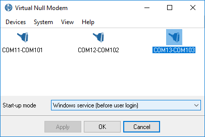
Fig. 7. The main program window.
The menus of Virtual Null Modem are located on the menu bar. The sub-menus of the main menu are Devices, System, View and Help. Each item in these menus is described in this section below. Some menu functions are also activated by pressing combinations of keys on the keyboard (called "Hotkeys" in this Help file)
Another way to access some edit menu functions is to click the right button of the mouse. See the help paragraphs on each function for more information. Hotkeys are described thus: "Ctrl+N" means that the user holds the Ctrl key down while simultaneously pressing the N key. The appropriate keyboard shortcuts and toolbar buttons are shown with each menu item.
After adding serial port pairs you should click the "OK" button to apply all changes. If it's first time, when you had added serial port pairs, then Virtual Null Modems software will install drivers and it can take few minutes on slow computers, please, wait while Virtual Null Modems software adding new virtual devices. This process will be accompanied by messages in the system tray like as fig. 8 and 9. This messages will apper for each virtual serial port in the list. Next time Virtual Null Modems software will not display this messages and will use drivers installed before.
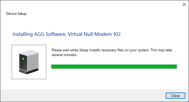
Fig. 8. Virtual Null Modems software adds a virtual serial port.
![]()
Fig. 9. Virtual Null Modems software installs drivers.
After installing drivers new virtual devices will appear in the device manager (see fig. 10).
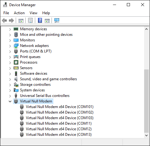
Fig. 10. Virtual Null Modems devices in the devices manager.
Now you can use these serial ports (a serial port number showed in brackets) in your software as a common hardware serial port.
Typical null-modem schematics
Null modem without handshaking
How to use the handshaking lines in a null modem configuration? The simplest way is to don't use them at all. In that situation, only the data lines and signal ground are cross connected in the null modem communication cable. All other pins have no connection. An example of such a null modem cable without handshaking can be seen in the figure below.

Fig. 11. Null modem without handshaking.
Compatibility issues
If you read about null modems, this three wire null modem cable is often talked about. Yes, it is simple but can we use it in all circumstances? There is a problem, if either of the two devices checks the DSR or CD inputs. These signals normally define the ability of the other side to communicate. As they are not connected, their signal level will never go high. This might cause a problem.
The same holds for the RTS/CTS handshaking sequence. If the software on both sides is well structured, the RTS output is set high and then a waiting cycle is started until a ready signal is received on the CTS line. This causes the software to hang because no physical connection is present to either CTS line to make this possible. The only type of communication which is allowed on such a null modem line is data-only traffic on the cross connected RxD/TxD lines.
This does however not mean, that this null modem cable is useless. Communication links like present in the Norton Commander program can use this null modem cable. This null modem cable can also be used when communicating with devices which do not have modem control signals like electronic measuring equipment etc.
As you can imagine, with this simple null modem cable no hardware flow control can be implemented. The only way to perform flow control is with software flow control using the XOFF and XON characters.
Null modem with loop back handshaking
The simple null modem cable without handshaking shows incompatibilities with common software. The main problem with this cable is that there is a possibility for the software to hang if it checks the modem signal lines in a proper way. I.e. with this null modem cable, good written programs will perform worse than badly written programs.
To overcome this problem and still be able to use a cheap null modem communication cable with only three lines in it, a fake null modem cable layout has been defined. The null modem cable with loop back handshaking resulted from this.

Fig. 12. Null modem with loop back handshaking.
The main purpose of this null modem cable is to let well defined software think there is handshaking available, with a null modem cable which has no provisions for it.
Compatibility issues
Consider first the DSR signal (pin 6). This input indicates that the other side is ready to start communicating. In the layout, the line is linked back to the DTR output (pin 4). This means, that the software doesn't see the ready signal of the other device, but its own. The same holds for the CD input (pin 1). The assumption is, that if software has been written to check the DSR line to test communication availability, it will probably also set the DTR output to indicate its own state. This is true for at least 99% of all serial communication software. This implies that at least 99% of all serial communication software is capable of faking its own DSR check with this null modem cable.
The same trick is used with the CTS input. In the original use, RTS is set, and then CTS is checked before starting the communication. By setting the RTS output (pin 7) the CTS input on the same connector (pin 8) is receiving clearance immediately. There is no possibility of a software hang up because of dangling RTS requests.
Other issues to consider
The null modem cable with loop back handshaking is often advised as the best low cost available null modem cable. But, is it really so good? The simple null modem cable without handshaking has the disadvantage that it does not permit proper written software to communicate with it. Software which is aware of the lack of handshaking signals can however use it without problems.
The null modem cable with loop back handshaking can be used with more software, but it has no functional enhancements over the simple cable! There is no way both devices can control data flow, other than by using XON/XOFF handshaking. If the software is designed for using hardware flow control it seems to work with this null modem cable, but on unpredictable moments, data loss may occur. This means that the null modem cable allows communication as long as no flow control is needed, but when data speeds reach the limit the receivers can handle, communication may stop immediately without an assignable reason. Therefore, although this null modem cable is cheap and easy to make, use it with care! Despite these warnings, this type of null modem cable has been used successfully between Windows 95/98/ME computers with a Direct Cable Connection.
Null modem with partial handshaking
The simple null modem cable and the null modem cable with loop back handshaking are useful, but have no provisions for hardware flow control. If it is absolutely necessary that hardware flow control is used, the null modem with partial handshaking can be an alternative.
Null modem with partial handshaking

Fig. 13. Null modem with partial handshaking.
Compatibility issues
This null modem cable is the best of two worlds. There is the possibility of hardware flow control without being incompatible with the original way flow control was used with DTE/DCE communication. Let us first consider the RTS/CTS flow control lines present on pins 7 and 8. As with the loop back null modem cable, these signals are not connected to the other device, but directly looped back on the same connector. This means, that RTS/CTS flow control is allowed to be used in the software, but it has no functional meaning. Only when the software at the other side checks the CD signal at pin 1, the RTS information will reach the other device. This would however be only the case in specifically developed software which uses the CD input for this purpose.
More important however is the cross connection of the DSR (pin 6) and DTR (pin 4) lines. By cross connecting these lines, their original function is simulated pretty well. The DTR output is used to signal the other device that communication is possible. This information is read on the DSR input, the same input used for this purpose with modem communication. Because of this cross connection, the DTR output line can be used for simple flow control. Incoming data is allowed when the output is set, and blocked if the output is not set.
Software using only the RTS/CTS protocol for flow control cannot take advantage of the partial handshaking null modem cable. Most software however will also check the DSR line and in that case when using the null modem cable with partial handshaking - the best possible hardware flow control can be achieved which is still compatible with the original use with modems.
Null modem with full handshaking
The most expensive null modem cable is the null modem cable suitable for full handshaking. In this null modem cable, seven wires are present. Only the ring indicator RI and carrier detect CD signal are not linked. The cable is shown in the following figure.

Fig. 14. Null modem with full handshaking.
Compatibility issues
The null modem cable with full handshaking does not permit the older way of flow control to take place. The main incompatibility is the cross connection of the RTS and CTS pins. Originally, these pins are used for a question/answer type of flow control. When the full handshaking null modem cable is used, there is no request anymore. The lines are purely used for telling the other side if communication is possible.
The main advantage of this cable is, that there are two signalling lines in each direction. Both the RTS and DTR outputs can be used to send flow control information to the other device. This makes it possible to achieve very high communication speeds with this type of null modem cable, provided that the software has been designed for it. Because of the high possible connection speed, this null modem cable can be used with Interlink to connect two MS-DOS PC's.
This is the type of cable Microsoft recommends for the direct cable connection in their knowledge base article. For the DB9 connector they also added a connection of DTR to CD on each connector but they didn't define this connection for the DB25 connector version and they also didn't mention the CD input in the descriptive text, so it is safe to leave the CD input disconnected.
Null modem with full handshaking #2
Same as the previous null-modem layout, but carrier detect CD signal are linked with the DSR signal. The cable is shown in the following figure.

Fig. 15. Null modem with full handshaking #2.
Devices menu
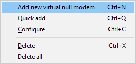
Fig. 16. The devices menu.
Add new virtual null modem
Hotkey: Ctrl+N
Right-click menu
It is used to create a virtual serial ports pair. After you selected this menu item, a dialog window will appear (fig. 17).
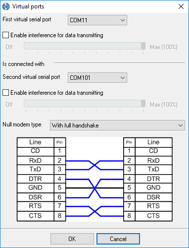
Fig. 17. The parameters dialog window.
You should select necessary port numbers from a drop down list. This list displays only ports, that has not been used early. If you want you can add additional interference to a outgoing data flow. Use a track bar for it. You can specify value from 0 to 100%. Click the "OK" button to accept your setting or the "Cancel" button to cancel the "Add" operation. By default, Virtual Null Modem software selects a first free ports pair. Our software can emulate few typical null-modem schematics. You can select a null-modem type from the corresponding drop-down box. The wires layout will be displayed on an image below the drop-down box. Emulated signal wires on the image are highlighted by blue color. Pin numbers are showed for a DB9 connector and are displayed for your convenience only, because virtual serial ports operate with signals only (RTS, CTS etc).
Quick add
Hotkey: Ctrl+Q
Right-click menu
Same as above, but dialog window doesn't appear and Virtual Null Modem uses default values for configuring a virtual serial ports pair.
Configure
Hotkey: Ctrl+C
Right-click menu
This opens the parameters window (fig. 17) for configured virtual null modem. This menu item is available only if a virtual null modem had been selected in the list.
Delete
Hotkey: Ctrl+X
Right-click menu
It will delete a selected virtual null modem from your list. This actions don't remove virtual null modem from your system, if it had been created early. You should click "OK" button to apply changes to your system. This menu item is available only if a virtual null modem had been selected in the list.
Delete all
Right-click menu
It will clear the virtual null modem's list. This actions don't remove virtual null modem from your system, if it had been created early. You should click "OK" button to apply changes to your system.
System menu
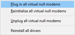
Fig. 18. The System menu.
Plug in all virtual null modems
Choose "System→Plug in all virtual null modems" to insert new virtual null modems to your system. This command can be useful if you created new virtual null modem and want to apply changes immediale.
Reinitialize all virtual null modems
Choose "System→Reinitialize all virtual null modems" to apply all changes to your system. This command can be useful if you changes your configuration and want to apply changes immediale. This command is mostly identical to the click of the "OK" button, but without closing application.
Unplug all virtual null modems
Choose "System→Unplug all virtual null modems" to remove all virtual null modems from your system, but nor from the list in the configuration window.
Reinstall drivers
Choose "System→Reinstall drivers" to try to install all virtual null modems drivers to your system.
View menu
Icons
There are four ways to display the icons in the virtual null modem's views - Big icon, Small icon, List and Table.
Arrange Icons
The way icons are arranged can help identify
Command line parameters
-p SerialNo
Plugs in a virtual serial port device with number SerialNo. SerialNo must be greater than zero. You should plug in 2 devices for creating one virtual null modem device.
-u SerialNo or 0
Unplug a virtual serial port device with number SerialNo. Please, specify 0 to unplug all devices enumerated so far.
-e SerialNo or 0
Eject a virtual serial port device with number SerialNo. Please, specify 0 to eject all the devices enumerated so far.
-i <INF_File> <Hardware_ID>
Install device driver INF_File for device Hardware_ID.
-ia
Install all Virtual Null Modem's devices drivers.
-r <Hardware_ID>
Remove device Hardware_ID.
-ra
Remove all Virtual Null Modem's devices drivers.
-s0
Don't show messages (verbose mode).
-s1
Write messages to Windows events log.
-s2
Show message box with messages (default).
-pa
This parameter plugs in all virtual serial port devices. The program reads port number from the HKEY_LOCAL_MACHINE\SOFTWARE\AGG Software\Virtual Null Modem branch from the "Ports" (REG_SZ) key. This key is created automatically by GUI application.
Key value example: 2,7,
Note: The order of parameters is very important. For examples, if you want to get silent install of drivers then you should use the following command prompt.
vnullmod -s0 -ia
FAQ and Known issues
Q: I want to control (create and delete) my virtual null modems.
A: You can do it with help of the command prompt.
Q: I can't open a virtual serial port.
A: If the "CreateFIle" function within your code uses the "COM%d" format string as a file name then you can open COM-COM9 ports only. You should use "\\.\COM%d" instead. In this case you can use any virtual serial port number.
Q: How to enumerate virtual serial ports?
A: If you need to enumerate virtual serial ports only then you can use SetupAPI functions and search all devices for class GUID {487ECAF4-213D-4d17-AA07-2F91078B619D}.
Unable to install Virtual Port Driver
The problems described below may occur when creating a virtual COM port configuration.
Problem 1
The program hangs at the moment of driver installation.
Some third-party antivirus programs may block the driver installation. Try temporarily disabling your antivirus.
Our users have reported issues with:
Avast Antivirus Free
NANO-Antivirus
Antiy-AVL
Note: If your antivirus trial period has expired and it reports that it is not working, it does not mean that it is completely disabled.
Problem 2
A virtual port won't show up in the Ports group (COM and LPT).
The virtual devices created with our program appear in a separate group named Virtual Serial Port.
Problem 3
The virtual port is available, but it is labeled with an exclamation mark in Device Manager.
This problem may occur when you try to create a port with a number that already exists in the system. To resolve the issue, try creating a virtual port with the number COM20. If you need to create a port with an already existing number (for example, COM1), then follow these steps:
1.Close all programs that might use COM1.
2.Find COM1 in Device Manager.
3.Right-click on it.
4.Select Properties and go to the Port Settings tab.
5.Click Advanced.
6.In the COM Port Number drop-down list select a free port and click OK.
7.Wait until the operating system applies the changes in the port number. You may need to reboot your computer.
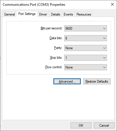
Fig. 1. COM port settings
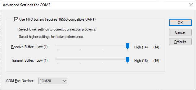
Fig. 2. Selecting a new COM port number
Problem 4
Unable to create a COM port. A new device won't show up in Device Manager, or it is labeled as unknown.
This problem is due to a failure to install the virtual port driver. Our driver has a valid digital signature, and there should be no problem installing it on all supported versions of Windows, including 64-bit editions.
Solution 1
The driver can only be installed with administrator rights. Please make sure that your account has the appropriate permissions.
Solution 2
The operating system cannot verify the digital signature of the driver. This problem may occur on older operating systems when there is no Internet connection, and no updates installed. You need to update your operating system or install updated certificates using rootsupd.exe in the program folder.
For 64-bit Windows: c:\Program Files (x86)\Virtual Null Modem\inf\
For 32-bit Windows: c:\Program Files\Virtual Null Modem\inf\
Solution 3
In operating systems released later than Windows Vista or Windows Server 2012, your PC or server's security policy may prohibit installing the driver for all new devices or the selected device classes. Such a policy may be implemented at the organization level if your computer is connected to the domain.
The easiest way to check your security policy is to run the rsop.msc snap-in:
1.Use the Windows key + R shortcut.
2.Type rsop.msc and press Enter.
3.The snap-in will check the existing security policy and display the enabled rules.
4.You need to make sure that there are no prohibiting or restricting rules in the group policy:
Computer Configuration - Administrative Templates - System - Device Installation - Device Installation Restrictions.
Policy settings:
•Prevent installation of removable devices.
•Prevent installation of devices not described by other policy settings.
Make sure you disable these settings during the installation of a new device. To change policy settings, contact your system administrator if necessary.
To configure policy settings, you can use the gpedit.msc snap-in.
Note: Group Policy Management Editor (gpedit.msc) is not installed by default in Starter, Home, and Home Premium editions. You will need to install it or use the registry editor.
1.Use the Windows key + R shortcut.
2.Type gpedit.msc and press Enter.
3.Go to Group Policy Editor: Computer Configuration - Administrative Templates - System - Device Installation - Device Installation Restrictions.
4.Disable the settings "Prevent installation of removable devices" and "Prevent installation of devices not described by other policy settings." Double-click on the name of the setting in the list and select Disabled.
5.In the program Virtual Null Modem, select System (Devices) - Reinstall drivers. Please wait until the installation process has ended.
6.Create the necessary virtual ports.
7.Save the settings.
8.Wait until the drivers for the new virtual ports are installed.
How to Use the Registry Editor
1.Type "regedit" (w/o quotes) in the Start menu search box
2.Right-click on the found Registry Editor application and select Run as Administrator.
3.Go to the branch HKLM\Software\Policies\Microsoft\Windows\DeviceInstall\Restrictions.
4.Set the value DenyRemovableDevices (REG_DWORD) to 0 (disabled).
5.Set the value DenyUnspecified (REG_DWORD) to 0 (disabled).
6.Restart your computer to apply the changes.
7.In the program Virtual Null Modem, select System (Devices) - Reinstall drivers. Please wait until the installation process has ended.
8.Create the necessary virtual ports.
9.Save the settings.
10.Wait until the drivers for the new virtual ports are installed.
Upon completion of virtual port installation, you may configure the initial values of the policy settings.
Solution 4
Make sure that driver installation from Windows Update is enabled.
1.Control Panel - System and Security - Advanced System Settings - Hardware - Device Installation Settings.
2.Select "Yes (recommended)".
3.Click OK and save the changes.
Solution 5
If the steps above do not help, the Windows may be corrupted. Then it is recommended to check the system files:
1.Type "cmd" (w/o quotes) in the Start menu search box.
2.Right-click on the Command Prompt application and select Run as Administrator.
3.In the command prompt, type "sfc /scannow" and press Enter.
4.The utility will check the Operating System for system file corruption.
5.Please wait until the system file check is complete.
Solution 6
Failure to install the driver may be due to a corrupted database of the device.
1.Follow steps 1 and 2 from solution 5.
2.To run the check, type in the command line: Dism /Online /Cleanup-Image /ScanHealth
3.To fix errors, type in the following: Dism /Online /Cleanup-Image /RestoreHealth